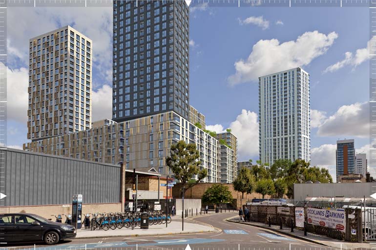
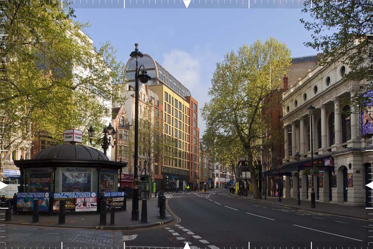
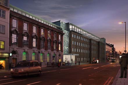
We work with architects, townscape consultants and planning experts to create Verified Views (VV) also known as Accurate Visual Representations (AVR) and Visually Verified Montages (VVM). These technically accurate images are used in planning applications and as supporting evidence for Townscape & Visual Impact Assessments.

Photo-montage & Verified Views

Architectural photo-montage is a computer generated image (CGI) that has been montaged into a photograph to show how a proposed development might look like in its surrounding context. We create these to be used for marketing and planning purposes.

Verified Views(VV) are specialist photo-montages that we create to a high level of verifiable accuracy and are used to support planning applications to help assess the visual impact of a proposed development. The images are supported by a methodology document which describes how the images were created. They are often requested by a local planning authority (LPA) for particularly large or tall developments or contextually sensitive projects and therefore need to be able to stand up to high levels of scrutiny during the planning process.


Our verified views are also used in pre-planning and planning phases to determine the maximum design envelope, testing maximum parameter plans and appropriate storey heights for new developments.

Our Verified View Methodology

1 Identify assessment point locations & views

These are typically chosen by the project team through consultation with the LPA and supplied to us. We then carry out a preliminary study to identify the view towards the development to identify any problems and determine the appropriate field of view for an informative photograph for agreement by the project team.

2 Photography

We will take high resolution photographs from the agreed viewpoints. Make a record of the camera's height, lens type, time, date and mark the camera's position on the ground. A photograph showing the marker and camera tripod in situ is also taken to allow the surveyor to identify its location for surveying.

3 Surveying

The photographs are analysed to identify key alignment points to be measured within each view. A survey brief is prepared, consisting of each views photograph to be surveyed, an assessment point location map and photographs. Our surveyor can then visit the site to survey each view's location and key alignment points.

4 3D Modelling

Using supplied design information, such as architectural drawings or 3D data we create a 3D model of the proposed development. The survey data for each camera's location and alignment points is imported into this 3d model and the model aligned with the survey data's co-ordinate system, so that they share the same spatial framework.

5 Camera Matching

We then create a virtual camera based on the real camera and lens combination used for each photograph. These are positioned in the 3D model using the surveyed camera location data and adjusted so that the surveyed alignment points align with the alignment points on the photograph verifying a match between the virtual camera and the photograph.

6 Rendering

We then render images from the virtual camera. This could be a simple wireline render to 'photorealistic' rendering where the 3D model would have materials applied and a lighting simulation to match the proposed developments appearance when viewed under the lighting conditions of the photograph.

7 Compositing

We then overlay the camera-matched rendered image of the 3D model on the views' original photograph and carefully identify background and foreground elements to the proposed development. The different elements of the photograph and the rendered image are then appropriately masked or extracted to different layers so that they can be combined together to create the final CGI for use as an accurate visual representation.

8 Document

We will issue a detailed methodology document along with the verified views which describes the process of how the images were created, data on the exact viewpoint locations and camera set up. This also includes images for each viewpoint as existing, proposed and if required, cumulative views, showing neighbouring consented schemes.


Verified View Classifications

The following are classification types that broadly define the purpose of a verified view / AVR in terms of the visual properties it represents. This classification is a cumulative scale in which each level incorporates all the properties of the previous level and is defined in the London View Management Framework (March 2012) SPG.
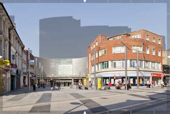
Level 0 Location and size of proposal shown as toned area.

Level 1 Location, size and degree of visibility shown as an occluded wireline image.
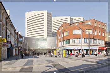
Level 2 As level 1 plus description of architectural form shown as shaded single uniform material.
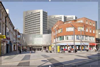
Level 3 As Level 2 plus use of proposed materials and lighting to match that of photograph shown as photorealistic rendering.

Methodology Guidelines

Our methodology is undertaken in line with current technical guidelines such as

  • Landscape Institute Advice Note 01/11
  • Guidelines on Landscape and Visual Impact Assessment 3rd edition (2013)
  • London View Management Framework (March 2012)

Get in Touch

Please fill in the contact form provided below to get in touch, and we will get back to you as soon as we can. If you don't wish to use this, feel free to call or email us about your enquiry